Underground fiber optic cable installation standards form the backbone of reliable network infrastructure. Poor installation practices lead to 60% of fiber network failures within the first five years.
At Clouddle, we see how proper installation techniques directly impact long-term network performance. Following established standards reduces maintenance costs by up to 40% and prevents costly service disruptions.
Fiber Optic Cable Installation Planning and Design
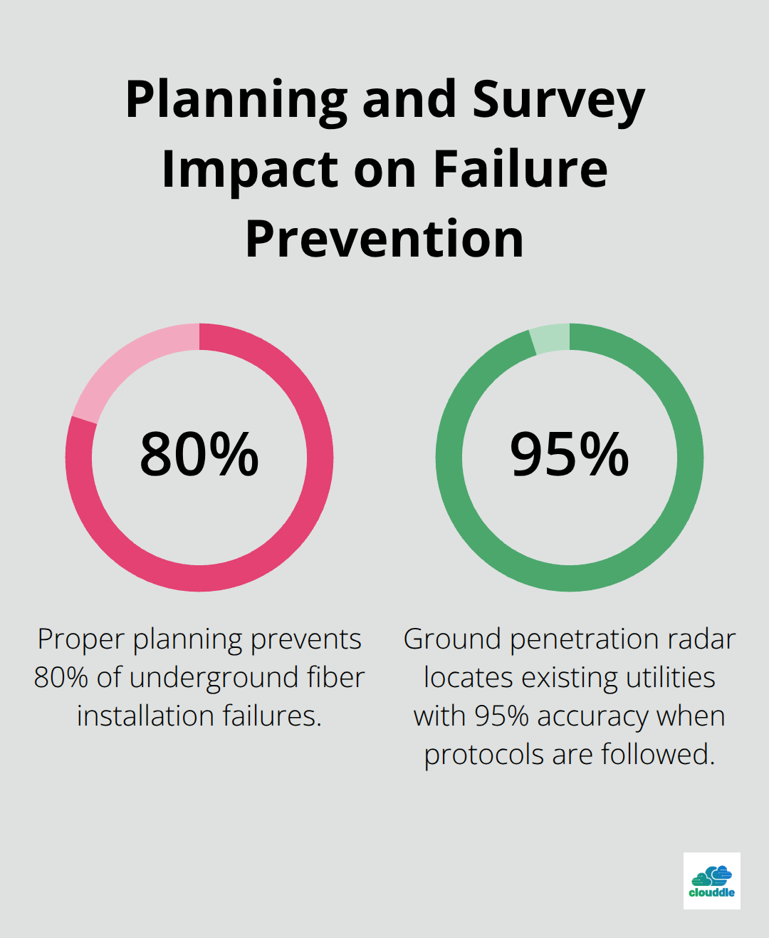
Proper planning prevents 80% of underground fiber installation failures according to FOA standards. Site surveys must identify all underground utilities within 50 feet of the planned route using ground penetration radar and the mandatory 811 Call Before You Dig service. Professional installers document soil composition, water table levels, and existing infrastructure during initial assessments. Rocky soil conditions require specialized trenching equipment, while high water tables demand waterproof conduit systems and modified burial depths.

Site Survey Requirements That Matter
Ground penetration radar (GPR) locates existing utilities with 95% accuracy when operators follow proper scanning protocols. The 811 service provides utility marking within 2-3 business days, but installers must hand-excavate within 24 inches of marked utilities to prevent damage. Survey teams measure exact distances between proposed routes and power lines, gas mains, and water systems. Professional surveys include photographic documentation of surface conditions, access points, and potential obstacles that affect installation methods.
Soil Analysis Determines Installation Success
Laboratory analysis reveals pH levels between 6.0-8.5 for optimal cable performance, while acidic soils below 5.0 accelerate jacket degradation. Clay soils retain moisture and create expansion issues, requiring deeper burial at 30-48 inches for direct-buried armored cables versus the standard 18-24 inches in stable soil. Sandy soils drain well but offer less mechanical protection, making conduit systems necessary for long-term reliability. Corrosive elements like salt or industrial chemicals mandate specialized cable jackets or protective conduit materials.
Environmental Factors Shape Installation Methods
Temperature variations between -40°F and 140°F impact cable performance, making proper depth selection critical for northern climates where frost lines reach 6 feet deep. High water tables require dewatering systems during installation and waterproof splice enclosures rated for continuous submersion. Coastal installations face salt spray corrosion (requiring marine-grade materials) and storm surge protection through deeper burial or concrete encasement. Seismic zones demand flexible conduit systems and expansion joints to accommodate ground movement.
Permit Requirements Define Project Scope
Installation permits require approval from local authorities, utility companies, and the Army Corps of Engineers for water crossings. NEC Article 770 mandates specific separation distances from power lines, while BICSI standards define pathway requirements. Harbor installations need additional marine permits, and coastal projects must account for tidal zones and storm surge protection. Documentation includes route maps, utility clearances, and environmental impact assessments before construction begins.
With planning complete and permits secured, the focus shifts to selecting appropriate installation methods and equipment for each specific site condition.
Underground Installation Methods and Best Practices
Direct burial armored cables require trenching depths of 30-48 inches in standard soil conditions, while conduit-protected cables need only 18-24 inches according to NEC Article 770 standards. Armored cables cost 40% more initially but eliminate conduit expenses and reduce installation time by 25%. However, conduit systems protect standard cables from rodent damage, which causes 30% of underground fiber failures within three years. Rocky soil conditions make conduit installation the only viable option since specialized trenching equipment cannot achieve proper depths for direct burial without excessive costs.
Trenching Equipment Selection Determines Project Success
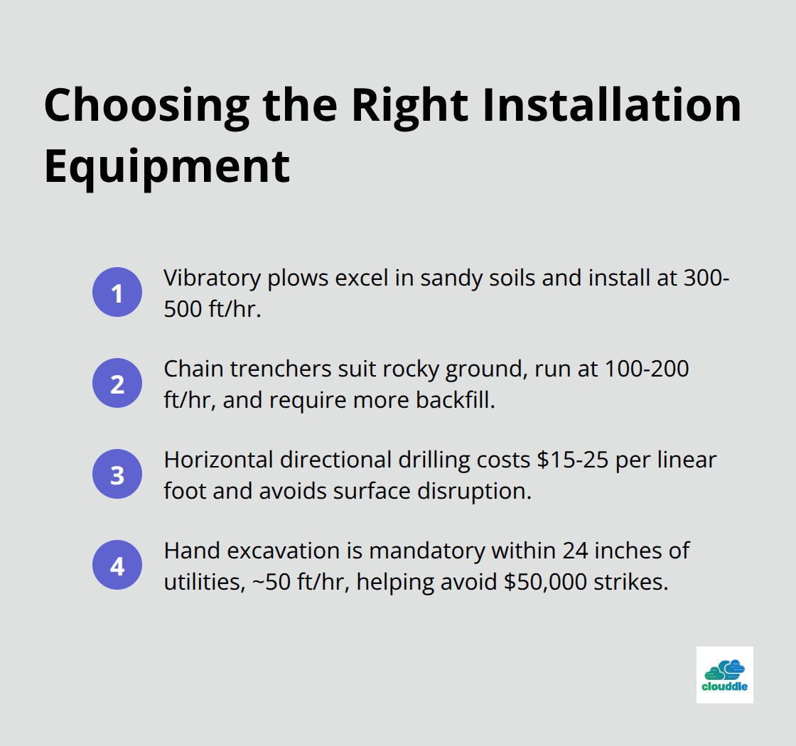
Vibratory plows work best in sandy soils and achieve installation speeds of 300-500 feet per hour, while chain trenchers handle rocky conditions at 100-200 feet per hour but create wider trenches that require more backfill. Horizontal directional drilling costs $15-25 per linear foot but avoids surface disruption under roads, driveways, and landscaped areas. Mini-excavators provide precision for utility crossings and tight spaces where larger equipment cannot operate safely. Hand excavation becomes mandatory within 24 inches of marked utilities, which reduces installation speed to 50 feet per hour but prevents costly utility strikes that average ,000 per incident.

Conduit Systems Offer Superior Long-Term Protection
HDPE conduit meets material, dimensional, workmanship and performance requirements for polyethylene conduit systems and resists chemical degradation better than PVC, which becomes brittle below 32°F. Proper conduit size requires 40% maximum fill ratios (meaning a 2-inch conduit accommodates up to 12 single-mode fibers with standard jackets). Pre-lubricated conduit systems reduce pulling tension by 45% and allow cable installation distances up to 2,000 feet with air-assisted blowing techniques. Duct banks with concrete encasement provide maximum protection in high-traffic areas but increase installation costs by 60% while extending cable life beyond 25 years.
Safety Protocols Prevent Costly Accidents
Warning tape placed 12 inches above buried conduit prevents accidental damage during future excavation work. Workers must wear hard hats, safety glasses, and high-visibility vests when operating trenching equipment (following OSHA regulations). Traffic management plans become mandatory for roadway installations, with designated “no go” zones around hazardous areas. Ground penetration radar confirms utility locations before mechanical excavation begins, while hand digging within 24 inches of marked utilities prevents damage to existing infrastructure.
Proper installation techniques require rigorous testing protocols to verify cable performance and system reliability before network activation. Professional fiber optic cable installation services should demonstrate proficiency with advanced techniques like fusion splicing and OTDR testing to ensure optimal network performance.
Testing and Quality Assurance Standards
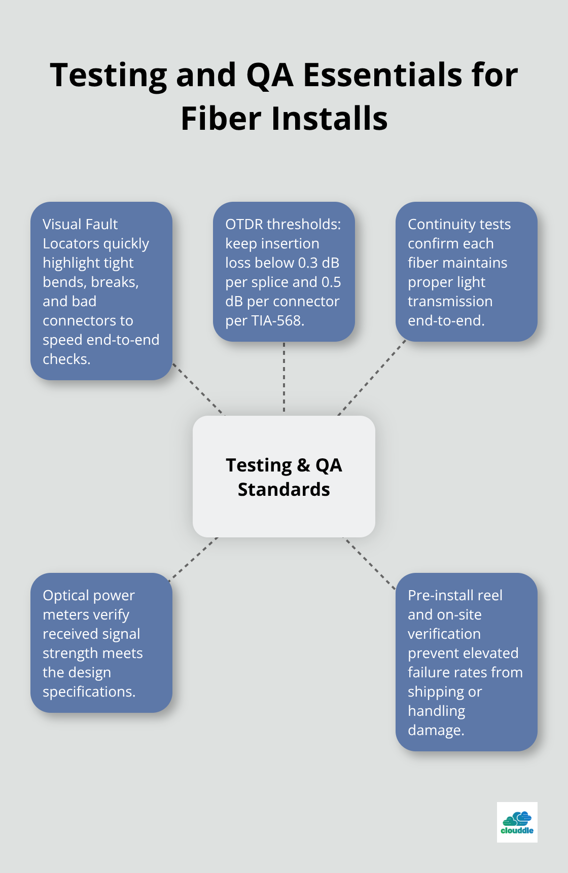
Visual Fault Locators locate visual faults including tight bends, breaks and bad connectors while accelerating end-to-end fiber checks. OTDR equipment reveals insertion loss values that must stay below 0.3 dB per splice and 0.5 dB per connector according to TIA-568 standards. Installers who skip reel tests face higher failure rates during post-installation verification. Continuity tests confirm each fiber strand maintains proper light transmission through the entire cable length, while optical power meters verify signal strength meets design specifications.
Pre-Installation Cable Tests Prevent Field Problems

Professional teams test every fiber individually rather than rely on sample tests, which miss defective strands that cause service interruptions. Cable manufacturers ship products with test certificates, but field conditions during transport can damage fibers. Temperature variations during shipment affect cable performance, making on-site verification essential before installation work begins. Technicians use Visual Fault Locators to identify core breaks that occurred during shipping or handling.
OTDR Analysis Identifies Network Performance Issues
OTDR trace analysis identifies splice locations, connector losses, and cable defects with measurement accuracy within 1 meter over 10-kilometer distances. Acceptable insertion loss budgets allow maximum 3.5 dB total loss for single-mode applications and 2.5 dB for multimode systems. Reflectance tests detect dirty connectors that cause fiber network problems (values must stay below -40 dB for single-mode connections). Professional test equipment costs $15,000-50,000 but prevents service calls that average $2,500 per incident.
Documentation Requirements Protect Installation Quality
Installers must document baseline measurements immediately after installation completion since environmental factors change performance over time. Test procedures require climate-controlled environments because temperature variations above 20°F affect measurement accuracy by 0.1 dB. Complete documentation includes splice loss reports, OTDR traces, and connector inspection photos that prove installation quality meets manufacturer warranties. Insurance requirements mandate proper test documentation to validate claims for installation defects or performance failures.
Final Thoughts
Underground fiber optic cable installation standards directly determine network longevity and performance outcomes. Projects that follow FOA guidelines experience 60% fewer failures during the first five years compared to installations that skip proper procedures. Site surveys with ground penetration radar and mandatory 811 utility marking prevent 95% of accidental utility strikes (which average $50,000 per incident).
Proper burial depths of 30-48 inches for armored cables and 18-24 inches for conduit-protected systems reduce maintenance costs by 40% over the network lifetime. OTDR tests with insertion loss values below 0.3 dB per splice and complete documentation protect installation quality while meeting manufacturer warranty requirements. Professional installation teams understand that shortcuts during implementation create expensive problems later.
Temperature variations, soil conditions, and environmental factors affect cable performance for decades after installation completion. At Clouddle, we provide comprehensive networking solutions that follow these rigorous installation standards. Our managed IT and networking expertise helps businesses maintain reliable connectivity through proper infrastructure planning and implementation.


