
Aerial fiber optic cable installation requires precise planning and execution to deliver reliable high-speed internet connections. The process involves complex technical considerations from route planning to final testing.
We at Clouddle have compiled this comprehensive guide to help network professionals navigate the installation process safely and efficiently. This step-by-step approach covers everything from initial site surveys to long-term maintenance strategies.
What Must You Plan Before Installing Aerial Fiber
Route Assessment and Obstacle Documentation
Successful aerial fiber installation starts with comprehensive route assessment that identifies every obstacle along the path. Walk the entire proposed route to document utility poles, power lines, trees, buildings, and existing cable infrastructure. The National Electrical Safety Code requires specific clearances from power lines, with fiber cables needing at least 40 inches of separation from 7.2 kV lines.
Document pole heights, span lengths, and structural integrity of existing infrastructure. Record GPS coordinates of each pole and measure exact distances between attachment points. This detailed survey prevents costly delays and safety hazards during installation.
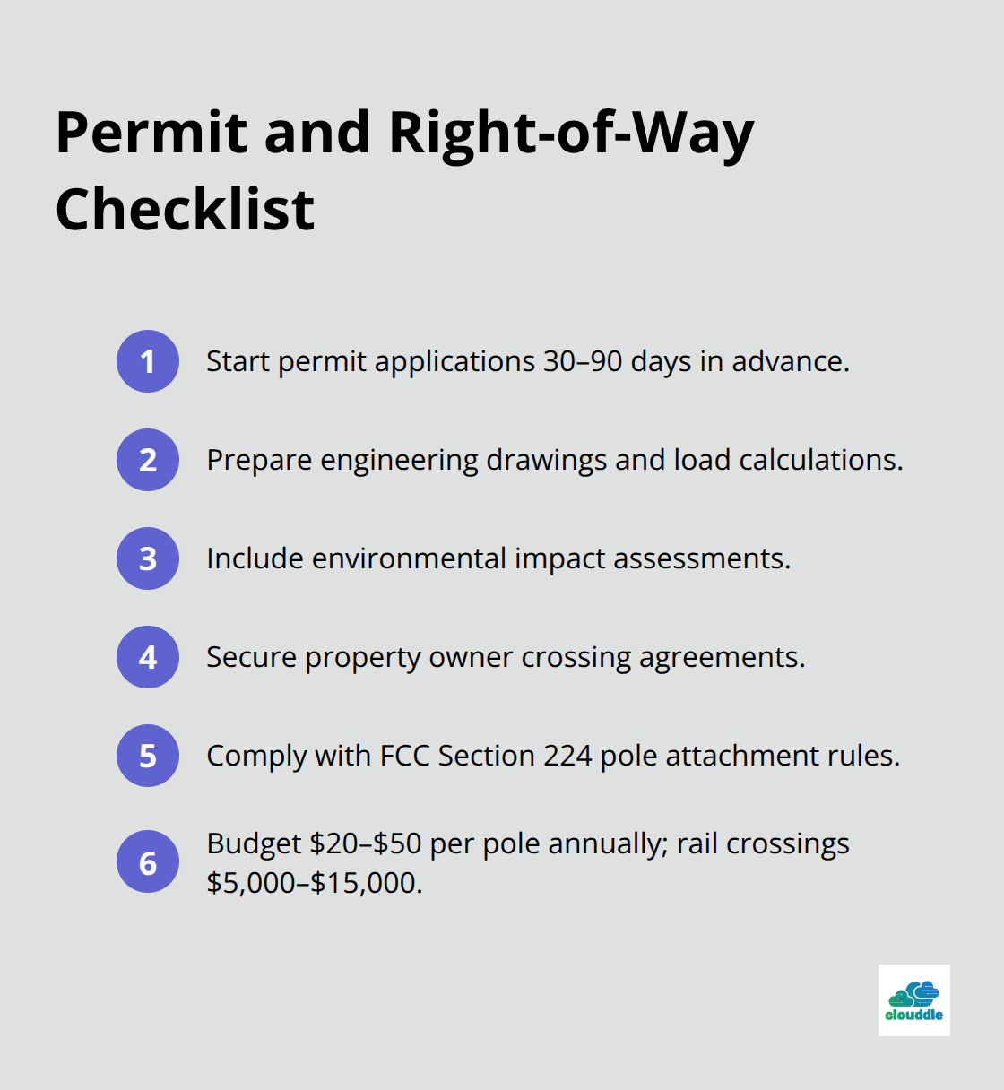
Permits and Right-of-Way Access
Contact local authorities early in the planning process, as permit approval can take 30 to 90 days depending on jurisdiction requirements. Most municipalities require detailed engineering drawings, load calculations, and environmental impact assessments before they issue construction permits.
Property owner agreements are mandatory for private land crossings, and utility companies must approve attachments to their poles. The Federal Communications Commission requires compliance with Section 224 regulations for pole attachment rights. Joint use agreements with existing utilities typically cost between $20 to $50 per attachment point annually (railroad crossings require special permits that can cost $5,000 to $15,000 per crossing).
Cable and Hardware Selection
All-Dielectric Self Supporting cables work best for aerial installations because they eliminate grounding requirements and allow closer proximity to power lines. Choose cables with polyethylene jackets treated with carbon black for UV protection, as untreated cables fail within five years of sun exposure.
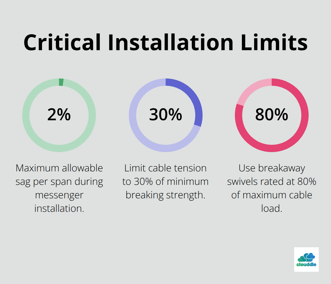
Cable diameter directly affects wind loading, with larger cables requiring stronger support structures. Messenger wire must handle wind and ice loads according to ANSI/ICEA P-79-561-2020 specifications. Calculate maximum tension at 30% of the cable’s minimum breaking strength to prevent damage. Dead-end hardware selection depends on span length (formed wire grips for spans over 300 feet and wedge anchor clamps for shorter distances).
With proper planning complete, the next phase focuses on the actual installation process and proven techniques that guarantee reliable cable deployment.
How Do You Execute Professional Aerial Fiber Installation
Pole Attachment and Support Structure Setup
Begin installation at the strongest pole in your route and work systematically toward weaker structures. Mount messenger wire first with formed wire dead-end grips rated for your calculated tension loads. The messenger must handle the required load capacity plus wind and ice loads specified in your calculations.
Install the messenger with 2% sag maximum across each span. Use a dynamometer to measure exact tension during installation. Position temporary supports every 150 feet on long spans to prevent excessive sag during cable placement.
Dead-end poles require guy wire reinforcement when they support spans over 400 feet or when corner angles exceed 30 degrees. This reinforcement prevents structural failure under maximum load conditions.
Cable Installation and Tensioning Methods
The moving reel method works best for unobstructed routes and allows installation teams to maintain consistent cable speed and tension. Mount the cable reel on a truck and pay off cable at walking speed while support crews guide it onto the messenger wire.
Never exceed 600 pounds of pulling tension during installation, as higher loads damage internal fibers. Use calibrated pulling winches with automatic tension monitoring to prevent overload conditions that compromise cable integrity. Cable is generally made with the fiber being about 1% longer than the cable to prevent tension on the cable elongating it and stressing the fiber.
The stationary reel method becomes necessary when obstacles block vehicle access or when you install above existing cables. Install pulling grips every 1,000 feet and use breakaway swivels rated at 80% of maximum cable load.
Splice Enclosure and Hardware Installation
Position splice closures at poles with adequate service loops of 20 feet minimum on each side for future maintenance access. Mount closures with galvanized steel brackets rated for 200-pound loads in 50 mph winds.
Fusion splicing provides superior connection quality, but requires specialized equipment and training. For link testing, measured insertion loss needs to be less than 6.10dB at 850nm and 3.85dB at 1300nm for the link to pass. Pre-terminated cables reduce installation time by 60% according to Fiber Optic Association data (though they create excess cable that requires proper storage loops).
Install vibration dampers on lightweight cables in windy areas to prevent fatigue damage to support hardware. Ground all metallic components every quarter mile with #6 copper wire connected to driven ground rods.
Safety protocols become paramount once installation begins, as aerial work presents unique hazards that require specialized protective measures and constant vigilance.
What Safety Measures Prevent Aerial Installation Accidents
Personal Protection and Equipment Standards
Aerial fiber installation requires specialized safety equipment that meets OSHA requirements for telecommunication workers. Hard hats rated for electrical work must withstand 2,200 volts and include chin straps to prevent loss during windy conditions. Class E safety boots with electrical hazard protection rated to 18,000 volts protect against accidental contact with energized lines.
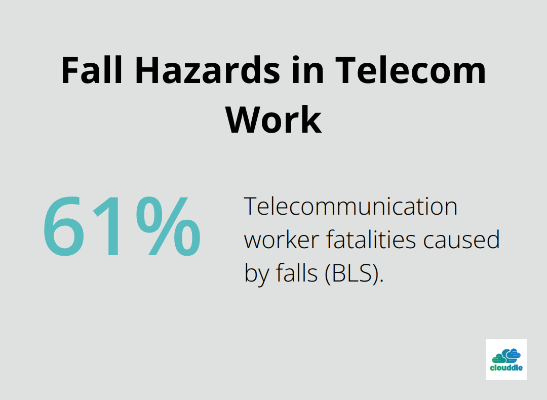
Full-body harnesses with shock-absorbing lanyards rated for 5,000-pound loads prevent fatal falls from heights above six feet. The Bureau of Labor Statistics reports that 61% of telecommunication worker fatalities occur from falls, which makes proper harness systems non-negotiable. Workers must inspect all safety equipment daily and replace worn components immediately, as compromised gear fails when protection becomes most critical.
Tool Safety and Electrical Protection
Insulated tools rated for 1,000 volts minimum prevent electrical accidents when workers operate near power lines. Voltage detectors and hot sticks allow safe distance verification of electrical hazards before crew members approach attachment points. Workers must test all electrical detection equipment before each use to verify proper operation.
Non-conductive fiberglass ladders replace metal versions near electrical infrastructure. Steel ladders conduct electricity and create deadly hazards when they contact power lines. Tool belts and equipment bags require non-metallic construction to prevent accidental electrical contact during aerial work.
Electrical Hazard Prevention
Power line contact causes significant worker fatalities according to NIOSH data, which makes electrical awareness critical for aerial installations. Workers must maintain 10-foot minimum approach distances from power lines that carry more than 50 kilovolts. Lower voltage lines require six-foot clearances, but crews should treat all lines as energized until proper testing equipment proves otherwise.
Install fiber cables in designated telecommunications space below power lines, never above electrical conductors. Ground all metallic messenger wires and hardware every 1,320 feet with #6 copper conductors connected to eight-foot ground rods driven to full depth. Steel components become energized during electrical faults and create deadly hazards without proper grounding systems.
Weather and Environmental Risk Management
Wind speeds above 25 mph make aerial installation extremely dangerous due to cable whipping and reduced worker stability. Lightning within 10 miles requires immediate work stoppage and crew evacuation to enclosed vehicles or buildings. Temperature extremes affect both worker safety and cable handling characteristics.
Cables become brittle below 14°F and require heated storage before installation to prevent cracking during handling. Ice accumulation adds significant weight to spans and creates slippery conditions on poles and equipment. Quarter-inch ice accumulation increases cable weight significantly, which potentially overloads support structures. Project managers must schedule installations during optimal weather windows and monitor conditions continuously throughout the project timeline.
Final Thoughts
Aerial fiber optic cable installation requires precise execution across every project phase. Route assessment, permit acquisition, and material selection create the foundation for network reliability. Professional techniques prevent system failures and protect workers from significant safety hazards.
Certified technicians deliver superior results through their expertise in load calculations and regulatory compliance. Amateur installers create costly problems that require expensive remediation work later. The Bureau of Labor Statistics confirms that proper safety protocols save lives and prevent project delays (while also reducing insurance costs for contractors).
Quality installation practices justify their initial investment through decades of reliable operation. Regular inspections identify problems before they cause service interruptions. Clouddle supports reliable fiber optic installations for hospitality, multi-family dwelling, and senior living industries through comprehensive networking solutions.

0 Comments