Understanding Your Fiber Installation Reality
Jumping into a fiber optic installation without truly understanding the environment is a classic rookie mistake. Sure, spec sheets and guides give you a baseline, but the real world is messy. I’ve talked to countless seasoned technicians, and they all say the same thing: the most expensive errors happen during planning, long before a single cable is pulled, usually because of a rushed or incomplete site assessment. Learning to spot these potential headaches is what separates a smooth deployment from a project that bleeds time and money.
This isn’t just about dodging bullets; it’s about making smarter, more strategic decisions right from the start. With the demand for high-speed connectivity booming, more businesses are making this critical investment. The global market for fiber optic cable was valued at a massive $13.32 billion in 2023 and is expected to climb to $25.09 billion by 2030. When the stakes are that high, you have to get it right the first time. You can learn more about these market dynamics in this detailed industry report.
Single-Mode vs. Multi-Mode: The Real-World Decision
One of your first and most important calls will be choosing between single-mode and multi-mode fiber. This isn’t just a technical detail; it’s a strategic decision that needs to be based on your actual needs, not just what’s theoretically possible.
- Single-Mode Fiber (SMF): Think of this as a laser beam zipping down a tiny, one-lane superhighway. Because the core is so narrow, the light signal stays focused, allowing it to travel for miles with minimal distortion and carry enormous amounts of data. This makes it the clear choice for connecting different buildings, linking data centers across a campus, or any situation where you need to future-proof your network for next-generation speeds.
- Multi-Mode Fiber (MMF): This is more like a multi-lane local road. It has a larger core that allows multiple light signals (or “modes”) to travel at once. However, over longer distances, these signals can spread out and weaken, a phenomenon known as modal dispersion. It’s a cost-effective and perfectly suitable option for shorter runs within a single building, such as connecting a server room to user workstations.
To help you visualize the differences and make the right call for your project, here’s a quick comparison of the two main fiber types.
| Fiber Type | Maximum Distance | Bandwidth | Cost | Best Use Cases |
|---|---|---|---|---|
| Single-Mode (SMF) | Up to 40 km (25 miles) or more | Virtually unlimited; easily supports 100 Gbps+ | Higher initial cost (cable and transceivers) | Long-haul networks, campus backbones, data center interconnects, future-proofing for high-bandwidth applications. |
| Multi-Mode (MMF) | Up to 550 meters (~1,800 feet) for 10 Gbps | Good for 1-10 Gbps, but limited by distance | Lower initial cost (cable and transceivers) | Intra-building connections, server rooms to workstations, short-distance data center links. |
As the table shows, the decision really comes down to balancing distance, bandwidth needs, and budget. While multi-mode is great for internal links, single-mode is the undisputed king for any long-distance or high-capacity requirement.
This infographic clearly visualizes the bandwidth difference between common cable types.
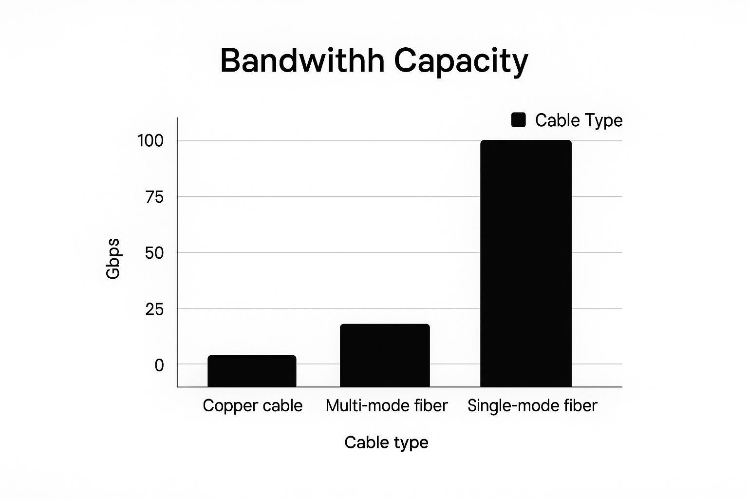
The leap in data capacity from traditional copper to fiber is substantial, but the jump from multi-mode to single-mode really drives home why SMF is the standard for networks built to last.
Beyond the Cable: Environmental and Structural Factors
The unique layout and conditions of your building will have a huge say in how to install fiber optic cable properly. A skilled installer doesn’t just see walls and ceilings; they see potential problems. They’re looking for crowded conduits that could make pulling cable a nightmare, sources of electromagnetic interference (EMI) from heavy equipment, or extreme temperature swings in a warehouse that could degrade the cable over time.
Thinking about these factors early on saves you from frustrating and costly fixes down the road. It’s the kind of practical knowledge that turns a good plan into a great installation. For a more thorough look at professional cabling approaches, feel free to explore our guide on data and fiber optic cabling solutions.
Tools That Actually Matter for Professional Results
A solid plan is a great start, but bringing it to life depends entirely on having the right equipment. When you browse tool catalogs, the number of gadgets can be dizzying, and every sales rep seems to have a “must-have” item. Let’s filter out the noise and focus on the tools that truly make a difference in the field, based on what seasoned installers use every day.
The reality is, you don’t need the most expensive version of every tool to achieve professional-grade results. The secret is to invest wisely in the items that have the biggest impact on the quality and long-term reliability of your work.
Core Installation & Termination Kit
When you’re learning how to install fiber optic cable, your termination and splicing kit is where precision is everything. This is not the place to cut corners. A dependable fusion splicer that delivers consistent, low-loss splices—ideally under 0.05 dB—is an investment that will serve you throughout your career. Along with it, you’ll need:
- A high-quality fiber cleaver: This is just as critical as the splicer itself. A sloppy cleave angle will lead to a bad splice, regardless of how advanced your splicer is. Aim for one with a blade life of over 40,000 cleaves.
- Fiber strippers and cutters: A three-hole stripper is essential for handling everything from the outer jacket down to the delicate acrylate coating in one smooth process.
- Isopropyl alcohol (99% pure) and lint-free wipes: Contamination is the number one enemy of a strong fiber connection. A tiny speck of dust can destroy your signal, making it absolutely necessary to clean every connector end-face.
Before we get into testing gear, let’s lay out a clear checklist of what you’ll need. This table covers the essential tools, what they’re for, and some tips from the pros to help you choose wisely.
| Tool Category | Essential Items | Estimated Cost | Professional Tips |
|---|---|---|---|
| Cable Prep & Splicing | Fusion Splicer, High-Precision Cleaver, Fiber Strippers | $1,500 – $8,000+ | Invest in a splicer with a low loss rate (<0.05 dB). A good cleaver is non-negotiable for clean splices. |
| Cleaning Supplies | 99% Isopropyl Alcohol, Lint-Free Wipes, Canned Air | $20 – $50 | Never reuse wipes. A “click cleaner” is a great field-friendly alternative for cleaning end-faces quickly. |
| Inspection & Testing | Fiber Inspection Scope, VFL, OLTS (Light Source & Power Meter) | $500 – $5,000 | A scope is mandatory, not optional. A VFL is a lifesaver for finding breaks and macrobends fast. |
| Hand Tools & Safety | Kevlar Cutters, Jacket Slitters, Safety Glasses | $50 – $200 | Always wear safety glasses—fiber shards are incredibly dangerous. Get cutters designed specifically for aramid yarn. |
This checklist covers the absolute essentials. As you gain experience, you’ll add more specialized tools to your kit, but starting with high-quality versions of these items will set you up for success on any job.
Testing and Verification Gear
Your work isn’t finished until you can prove the link performs flawlessly. For this, you need diagnostic tools that provide clear, actionable data. This is how you can see exactly how your newly installed network is performing.

This screenshot shows a modern fiber testing tool, like those from Fluke Networks, which is vital for verifying installation quality and diagnosing problems. These devices generate detailed reports on signal loss, reflectance, and cable length, confirming that your work meets industry standards. This level of detail is also crucial when your cabling needs to support other network infrastructure. For instance, a rock-solid physical layer is the foundation for high-performance wireless access, a topic we explore in our article on managed Wi-Fi services.
At the very least, your testing kit must contain:
- Optical Loss Test Set (OLTS): This pair of tools, a light source and a power meter, measures the total light loss across your link. It’s your ultimate pass/fail check.
- Visual Fault Locator (VFL): A simple but incredibly useful tool. This pen-sized red laser helps you quickly spot breaks, faulty splices, and sharp bends by making the escaping light visible to the naked eye.
- Fiber Inspection Scope: You can’t fix what you can’t see. This microscope lets you inspect connector end-faces for any dirt, oil, or damage before you make a connection.
Planning Routes That Don’t Fight Back
This is where a smooth fiber installation can quietly go off the rails—long before you even unspool the first inch of cable. An experienced installer doesn’t just see a path from Point A to Point B; they see a gauntlet of potential obstacles. The key is to shift your mindset from just pulling cable to strategically placing it. Reading building blueprints is a good start, but they rarely tell the whole story. Architects design for aesthetics and function, not for the low-voltage technician who has to navigate the messy reality of what comes after.
Reading Between the Lines of a Building
Your first walkthrough is an intelligence-gathering mission. Forget what the drawings show for a moment and look for the real-world challenges. Older buildings are notorious for surprises like concrete fire breaks hidden above a drop ceiling or asbestos-containing materials that require specialized handling and permits. In a recent project in a historic downtown building, our team found that the “empty” conduit marked on a 50-year-old blueprint was actually packed with legacy coaxial cable. That “easy” pull instantly became a complex project involving careful removal and coordination.
A smart approach to planning your fiber optic installation involves looking for:
- HVAC ductwork and plumbing: These are non-negotiable obstacles. Plan routes that go around them with plenty of clearance.
- Sources of EMI: While fiber is immune to electromagnetic interference (EMI), your path might run alongside sensitive copper lines for other systems. Be a good partner and avoid creating issues for other trades.
- Future access points: Don’t box yourself in. Make sure your route is accessible for future maintenance without requiring demolition. That means avoiding routes above hard-lid ceilings whenever possible.
Documenting for Your Future Self
The process of how to install fiber optic cable is a multi-stage affair, where effective planning is the foundation for everything that follows. The core of this planning phase is figuring out the best route and the right type of cable, considering factors like physical terrain and the data needs of the network. You can explore more on these foundational steps of fiber installation.
This initial groundwork is not just about avoiding problems; it’s about creating a clear, documented plan. Take photos, make detailed notes, and mark up your blueprints with the actual conditions. This documentation is your single source of truth and becomes invaluable when coordinating with electricians, HVAC techs, or general contractors. When you can show someone a photo of the obstruction you’re trying to avoid, the conversation becomes much more productive. It also helps in calculating a realistic timeline that accounts for these real-world hurdles, ensuring your project stays on track and on budget.
Cable Installation Techniques From the Field
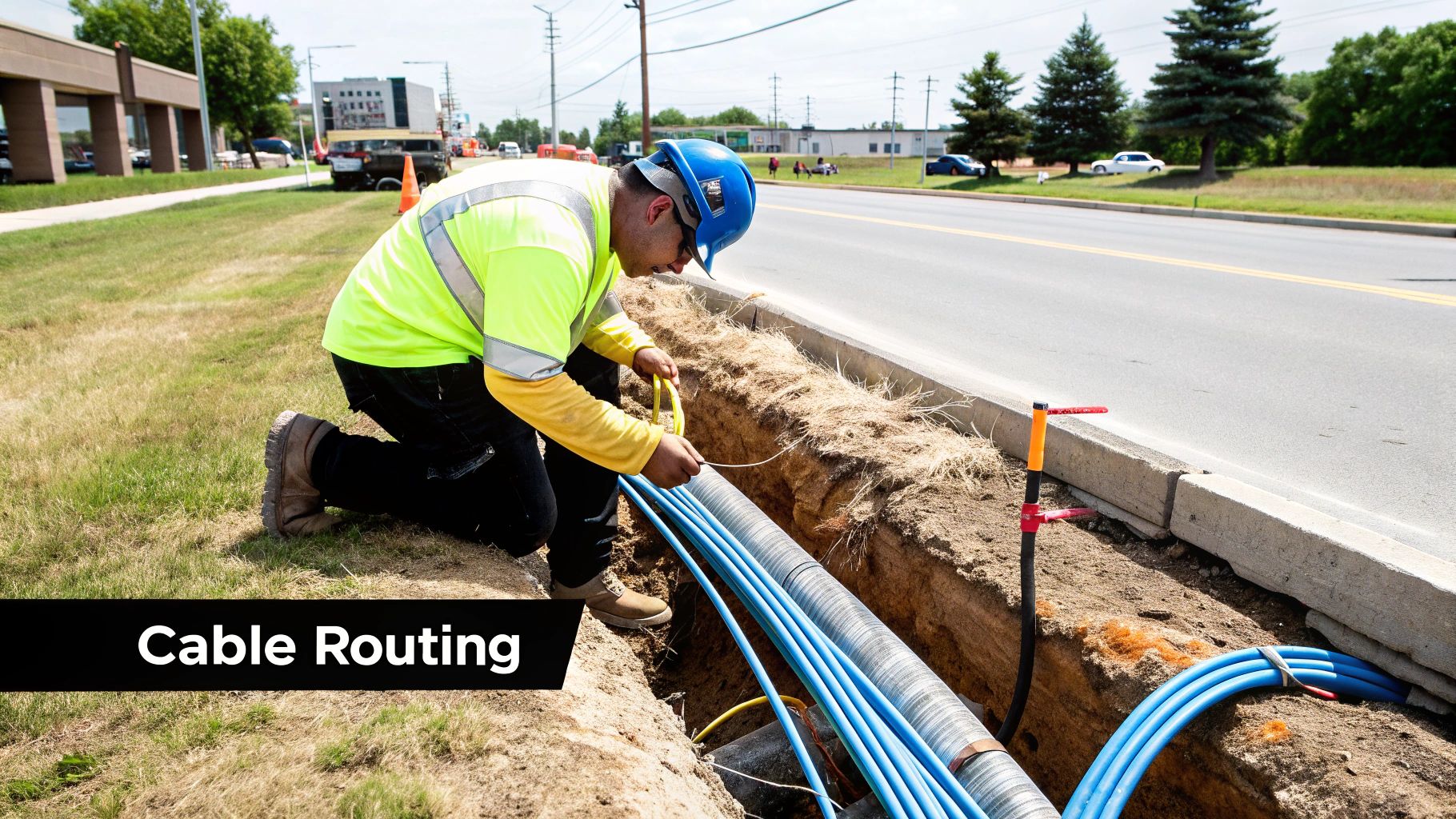
Once you’ve mapped out your cable route, it’s time to get your hands dirty. This is where the plans on paper meet the reality of a cramped, dusty ceiling space. The guiding principle when you install fiber optic cable is to use finesse, not force. While fiber is incredibly strong under tension—stronger than steel by weight—it can be surprisingly fragile if bent too sharply or twisted. Every pull, corner, and snag is a potential failure point that might not show up until you’re doing final tests.
The main goal is to prevent microbends, which are tiny, nearly invisible kinks in the fiber that can seriously disrupt the light signal. These are usually caused by pulling too hard or bending the cable too tightly, leading to signal loss that can be a real headache to find and fix later.
Mastering the Pull
One of the biggest mistakes I see new technicians make is trying to brute-force a cable through a conduit. That’s a surefire way to cause damage. The real secret is a smooth, consistent pull that respects the cable’s physical limits. Most manufacturers specify a maximum pulling tension, which is often around 600 pounds for outdoor cables but significantly less for indoor ones. Going over this limit can stretch the fibers and cause permanent damage.
To keep the pull safe and easy, here are a few tips I’ve picked up over the years:
- Use the Right Lubricant: A quality, water-based cable pulling lubricant is a lifesaver. It can cut down friction by over 70%, which means you need far less force. Apply it liberally at the start of the run and every 10-15 feet on longer pulls.
- Communicate Constantly: For any pull involving more than one person, clear communication is essential. Use two-way radios to coordinate your actions. The person feeding the cable needs to make sure it comes off the spool cleanly without twisting, while the person pulling should maintain a steady pace and stop immediately if they feel any resistance.
- Leverage a Pulling Eye or Grip: Never pull on the cable jacket itself. Always attach a pulling eye (also known as a Kellems grip) to the cable’s internal strength members, like the aramid yarn. This ensures the force is applied to the strongest part of the cable, not the delicate glass fibers inside.
Navigating Corners and Trays
Corners are the natural enemy of a clean cable pull. Each bend adds a significant amount of friction and increases the risk of exceeding the cable’s minimum bend radius. For most indoor fiber, this is about 10 times the cable’s outer diameter. A good rule of thumb is to never bend it tighter than the curve of a coffee can.
When a route has several corners, it’s often smarter to pull the cable to an intermediate point first. Coil the cable carefully in a large “figure-eight” on the floor—this prevents twisting—and then begin a new pull from that spot. This technique effectively resets the pulling tension and gives you much better control over the rest of the installation.
Splicing and Termination That Actually Lasts
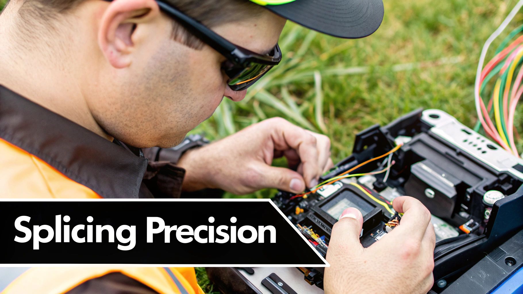
Once you’ve carefully pulled your cable, you’ve reached the most precise part of the job: splicing and termination. This is the moment that truly defines your installation’s long-term performance. It’s a game of micrometers where a single speck of dust can completely undo all your hard work. Knowing how to splice and terminate correctly isn’t just a technical skill—it’s the art of creating connections that will hold up under real-world conditions for years.
Mastering the Fusion Splice
For permanently joining two fibers, a fusion splice is the industry standard. The process involves perfectly aligning two glass ends and then melting them together with an electric arc. Modern fusion splicers have made this process much more automated, but the quality of your splice still comes down to your prep work. I can’t stress this enough: contamination is the number one enemy of a good splice.
Here’s what I’ve learned makes a real difference in the field:
- A Pristine Workspace: Even if you’re in a dusty construction zone, create a clean bubble for yourself. I always lay down a clean mat and keep my tools organized. A small folding table can be a lifesaver.
- The Perfect Cleave: Your splicer can’t fix a bad cleave. After stripping the fiber, clean it with 99% isopropyl alcohol and a lint-free wipe—always wiping in one direction. Then, use a high-quality cleaver to create a perfectly flat end face at a 90-degree angle. A poor cleave is the most common reason for a high-loss splice.
- Trust, But Verify: A good splicer will give you an estimated loss reading, but don’t just take its word for it. After the splice is complete and you’ve protected it with a heat-shrink sleeve, always test the connection with an Optical Time Domain Reflectometer (OTDR). This will verify the actual loss, which should ideally be below 0.05 dB.
Connector Termination That Works
When you need to connect the fiber to a piece of equipment, you’ll be terminating it with a connector. Using factory-polished pigtails is a reliable option, but sometimes you have to install a connector directly onto the fiber in the field. This is where many installers run into trouble with signal loss.
The most common connector types you’ll work with are LC (Lucent Connector) and SC (Subscriber Connector). LCs are smaller and common in high-density areas like data centers. The larger, more rugged SC connectors are often used in telecommunications. Choosing the right one is as simple as matching the ports on the equipment you’re connecting to.
The secret to a solid field termination is cleanliness and proper polishing. After you attach the connector, the fiber end-face has to be polished to a mirror-smooth finish. Any scratches or debris will create back reflection and insertion loss, crippling your network’s performance. My advice? Always inspect every single connector with a fiber scope before plugging it in—what you can’t see can definitely hurt your signal.
Testing That Proves Your Work
The job isn’t truly finished just because the last connector has been crimped. A professional installation is backed by solid proof, and that means going far beyond a simple continuity check. This is the stage where you verify that every single splice, termination, and cable run performs up to strict industry standards. Think of comprehensive testing as your quality guarantee—it protects you from costly callbacks and gives your client undeniable evidence of a job well done. It’s the final, and most critical, step when you **install fiber optic cable**.
Basic vs. Certification Testing
It’s important to understand the distinction between a quick check and full-blown certification. They serve different purposes and are appropriate for different types of jobs.
- Basic Verification: This typically involves using a Visual Fault Locator (VFL) to spot obvious light leaks from breaks and an Optical Loss Test Set (OLTS) to measure the total signal loss across the link. This is often called “Tier 1” testing and is usually sufficient for smaller projects to confirm the link is up and running.
- Full Certification: Known as “Tier 2” testing, this adds an Optical Time Domain Reflectometer (OTDR) to the mix. An OTDR provides a detailed graphical “picture” of the entire cable run. It shows you the performance of each individual component—splices, connectors, and even tight bends. It delivers precise loss measurements and pinpoints the distance to any faults, creating a performance baseline for any future troubleshooting. This level of testing is mandatory for most commercial and enterprise-level projects.
Interpreting Your Results
While an OLTS gives you a simple pass/fail on the total link loss, an OTDR tells you the story of why it passed or failed. From experience, a well-executed fusion splice should have a loss of less than 0.1 dB, and a good connector should be under 0.5 dB. If you see high-loss events or reflective “ghosts” on the OTDR trace, you’ve got a problem. These are classic signs of issues like dirty end-faces, bad cleaves, or bends that are too tight and need to be addressed.
Properly documenting these results is just as important as getting them. Creating thorough test reports not only validates the quality of your work but also provides a vital record for maintaining the network over its lifespan. As networks grow more complex with concepts like software-defined networking (SDN) and network function virtualization (NFV), this documentation becomes even more valuable. For more on how the industry is changing, you can read about trends in the fiber optic market. Ultimately, this data forms the foundation for effective security, a topic we cover in more detail in our guide to network security monitoring tools.
Key Takeaways for Installation Success
Learning how to install fiber optic cable is a journey from the textbook to the job site. It’s really about building the right habits that separate a decent installation from a truly professional one. Success isn’t about a single heroic moment; it’s the result of your consistent commitment to precision, careful planning, and protecting the cable throughout the entire project. From the first site walk to signing off on the final test report, every detail really does matter.
The Installer’s Mindset
A successful project always starts with the right frame of mind. You have to treat every cable with respect, knowing that the delicate glass inside is the lifeblood of a modern network. This means never cutting corners on the three pillars of a quality job:
- Patience: Rushing a pull or a splice is just asking for trouble. Take your time to properly lubricate conduits, use a “figure-eight” coil to manage slack during long runs, and make sure your workspace is spotless before you even think about termination.
- Precision: Every single connection counts. A perfect cleave, a squeaky-clean connector end-face, and a verified low-loss splice are the non-negotiable signatures of excellent work.
- Proof: Your work isn’t finished until you can prove it’s done right. Documenting everything with thorough OTDR and OLTS test results validates your installation, gives the client peace of mind, and protects you if issues pop up down the road.
Avoiding Costly Pitfalls
Even the most experienced technicians can fall into common traps if they get complacent. You have to stay vigilant and watch out for these project-killers:
- Exceeding Bend Radius: Bending a cable tighter than a coffee can creates microfractures and kills your signal. Always, always respect the 10x cable diameter rule for standard fiber. Don’t eyeball it; be mindful of every corner and pathway.
- Contamination: Dust, oils from your skin, and random debris are the mortal enemies of a fiber network. Get into the habit of inspecting and cleaning every single connector before you mate it. No exceptions.
- Ignoring Pull Tension: Simply yanking a cable is a recipe for disaster. Using a tension gauge and the correct pulling grip ensures you don’t stretch the fiber, which can cause permanent, invisible damage that will haunt the network for years.
Ultimately, your reputation is built on the reliability of your work. By making these principles second nature, you ensure every installation is a testament to your skill and professionalism.
For businesses that need this level of quality but don’t have in-house expertise, working with a managed solutions provider is the way to go. Clouddle Inc. offers complete fiber optic solutions, making sure your network infrastructure is installed to the highest professional standards and ready for whatever the future holds.


