
Underground fiber optic cable installation requires precise planning and execution to build reliable network infrastructure. Poor installation practices lead to 40% of fiber network failures within the first five years.
We at Clouddle have compiled this comprehensive guide covering every step from initial site surveys to final testing procedures. Follow these proven methods to avoid costly mistakes and achieve long-term network performance.
What Should You Plan Before Breaking Ground
Successful underground fiber installation starts with three non-negotiable phases that determine project success or failure. Skip any of these steps and you face delays, cost overruns, and potential safety hazards that plague 60% of rushed installations according to the Fiber Broadband Association.
Site Survey and Route Optimization
Professional site surveys reduce installation costs by 25-30% through accurate route planning and obstacle identification. Walk the entire installation path with a GPS unit to document elevation changes, soil conditions, and access points. Hard clay soil requires specialized equipment that costs $200-400 more per day than standard machinery. Rocky terrain increases installation time by 40-60% compared to standard soil conditions.
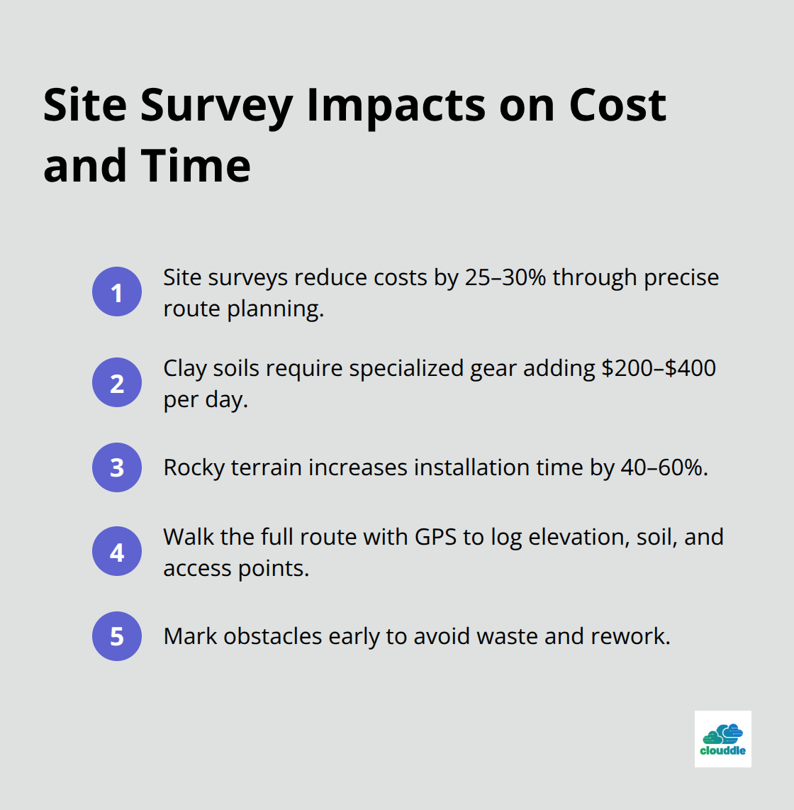
Document existing landscaping, driveways, and structures that affect cable placement. Measure distances precisely with fiberglass measuring tapes to calculate exact cable lengths and avoid expensive waste. Mark all potential obstacles on detailed site maps for reference during installation.
Permit Acquisition and Utility Location
Contact your local 811 service 72 hours before excavation to mark underground utilities at no cost. Ground Penetrating Radar surveys cost $300-500 per day but prevent utility strikes that cause significant damage. Obtain excavation permits from municipal authorities, which typically cost -200 and require 5-10 business days for approval.
Hand excavate within 24 inches of marked utilities to prevent damage to gas, electric, and water lines. Schedule utility location during dry weather conditions for maximum accuracy, as wet soil reduces GPR effectiveness by 30-40%.
Equipment and Material Selection
Choose loose tube armored cables for direct burial applications, as they withstand 1,000 pounds per square inch without conduit protection. High-density polyethylene conduit adds $2-4 per linear foot but simplifies future maintenance and cable additions. Rent narrow-width trenchers that create 4-6 inch wide trenches to minimize surface disruption and restoration costs.
Purchase rated grips for 150% of your cable weight to prevent installation damage. Stock fusion equipment and OTDR devices on-site to avoid project delays from equipment failures. Understanding your network infrastructure requirements helps determine the right equipment specifications for your installation. With your planning complete and materials ready, the actual installation process begins with proper excavation techniques.
How Do You Execute the Installation
Proper excavation technique determines installation success more than any other factor. Use narrow-width trenchers that create 4-6 inch trenches at 24-30 inch depths for residential installations and 36-42 inches for road crossings. Vibratory plows work best in sandy soil conditions but struggle with clay that exceeds 15% moisture content.
Rent hydraulic excavators for rocky terrain where trenchers fail, and accept the 40% time increase over standard machinery. Hand excavate the final 18 inches near marked utilities to prevent damage. The 2024 Common Ground Alliance data shows an increasing trend of total damages, with the CGA Index rising from 94 to 96.7.
Trenching Methods for Different Soil Types
Sandy soil allows trenchers to operate at maximum speed with minimal blade wear. Clay soil requires slower speeds and frequent blade cleaning to maintain cut quality. Rocky conditions demand specialized carbide-tipped blades that cost $300-500 more but prevent equipment damage.
Test soil moisture before equipment selection (wet clay above 15% moisture destroys trencher productivity). Schedule excavation during dry periods when possible to reduce equipment costs and improve cut precision.
Cable Placement Without Damage
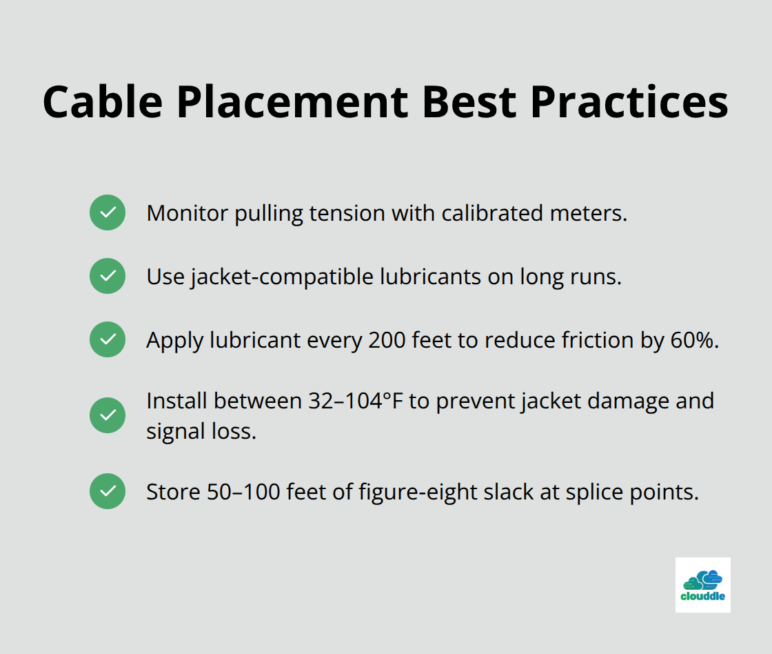
Monitor tension continuously during installation with calibrated meters that prevent exceeding manufacturer specifications. Never exceed the maximum pulling load rating, and on long runs, use proper lubricants that are compatible with the cable jacket.
Apply lubricant every 200 feet to reduce friction by 60% and prevent jacket damage. Install cables during temperatures between 32-104°F as extreme conditions cause jacket cracking and signal loss. Use figure-eight slack storage at splice points with 50-100 feet of extra cable to accommodate future maintenance without new sections.
Splice Enclosure Installation
Position splice enclosures 6 inches above finished grade to prevent water infiltration that causes 25% of network failures within three years. Fusion splice single-mode connections with loss targets below 0.05 dB per splice with automated fusion equipment.
Test each splice immediately with an OTDR to verify performance before sealing enclosures. Install fiber management trays that prevent bend radius violations below 10 times the cable diameter. Use gel-filled closures rated IP68 for underground applications as they resist moisture penetration for 25+ years compared to 5-7 years for standard enclosures.
Once installation completes, comprehensive testing validates network performance and identifies potential issues before system activation.
How Do You Verify Network Performance
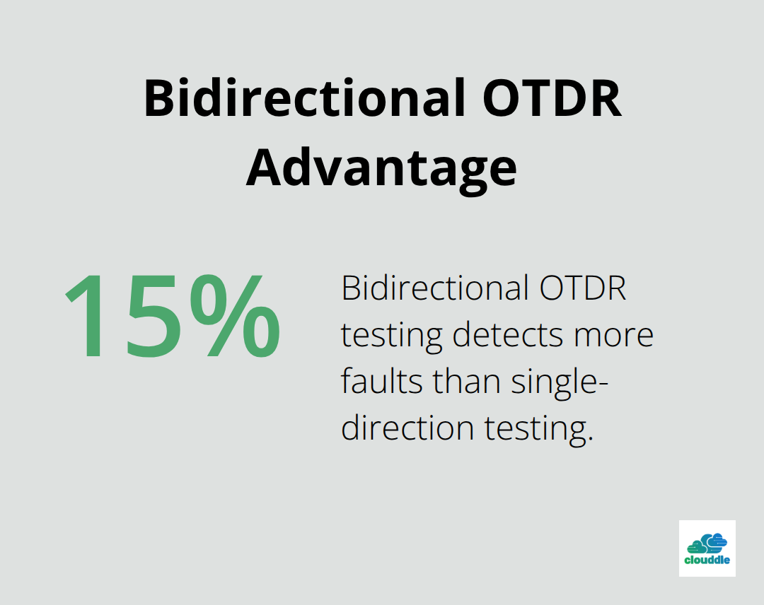
OTDR tests must begin immediately after splice completion to identify problems before backfill. Set your OTDR to match the installed fiber wavelength (1310nm for multimode, 1550nm for single-mode) and use launch cables that exceed 500 meters to eliminate dead zones. Test from both directions on every fiber strand as bidirectional tests reveal 15% more faults than single-direction tests according to the Fiber Optic Association.
Record baseline measurements that show minimal loss for optimal performance. Document every anomaly location with GPS coordinates for future maintenance reference.
Loss Budget Verification and Performance Standards
Calculate total system loss budget before tests begin with target values of 0.35 dB per kilometer for single-mode fiber at 1550nm wavelength. Measure insertion loss at multiple wavelengths with calibrated power meters that provide accuracy within ±0.02 dB. Reject any connections that exceed 0.75 dB total loss as they indicate contamination or mechanical damage that requires immediate correction. Test return loss with targets above 55 dB for APC connectors and 50 dB for UPC connections. Complete end-to-end tests at maximum and minimum wavelengths to verify performance across the entire spectrum.
Documentation Requirements for Future Maintenance
Create detailed as-built drawings that show exact cable depths, splice locations, and deviation from original plans within 12 inches accuracy. Record OTDR traces in electronic format with measurement data, test equipment serial numbers, and technician certifications for warranty compliance. Document fiber assignments with color-coded maps that match physical cable markings to prevent confusion during future additions. Include soil conditions, restoration notes, and access restrictions that affect maintenance operations. Store all documentation in waterproof containers at each splice location and maintain digital copies with GPS coordinates for rapid fault location. Proper documentation significantly reduces repair time when network performance issues occur.
Final Thoughts
Underground fiber optic cable installation requires precise execution at every stage to prevent the 40% failure rate that affects rushed projects. Professional installers maintain burial depths of 24-36 inches, monitor cable tension with calibrated equipment, and conduct bidirectional OTDR tests that detect 15% more faults than single-direction methods. These practices separate successful installations from costly failures that plague inexperienced teams.
Effective maintenance schedules include quarterly visual inspections of splice enclosures and annual OTDR performance tests to catch problems before service interruptions occur. Detailed as-built documentation with GPS coordinates reduces repair time by 40-50% when network issues arise. Gel-filled closures need replacement every 20-25 years (preventive maintenance that extends system life significantly).
Professional installation costs -35 per linear foot but eliminates the technical risks and safety hazards that affect DIY projects. Certified technicians use specialized fusion equipment, OTDR devices, and safety protocols that prevent utility strikes and equipment damage. For businesses that need reliable network infrastructure, we at Clouddle provide comprehensive solutions that combine networking expertise with ongoing support services.


0 Comments